Wybierz kraj
Polska Anglia
Nasze produkty na świecie
Austria, Azerbejdzan, Białorus, Belgia, Bułgaria, Kanada, Estonia, Finlandia, Francja, Gruzja, Niemcy, Wegry, Kazachstan, Łotwa, Litwa, Mołdawia, Holandia, Norwegia, Portugalia, Rumunia, Słowacja, Hiszpania, Szwecja, Ukraina, Wielka Brytania, USA
Products Air handling unitsEVO-PDiscover Klimor EVO technology

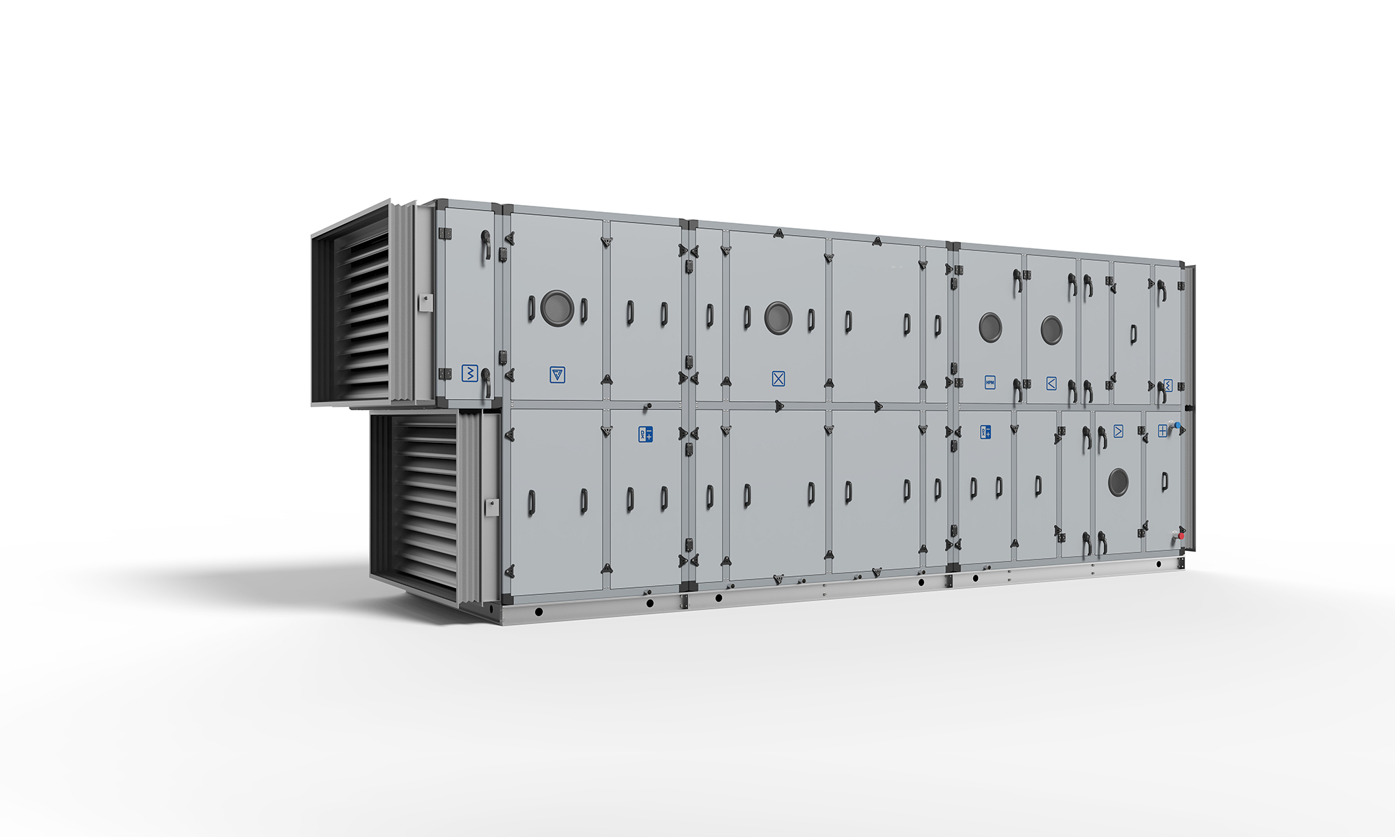
EVO-P

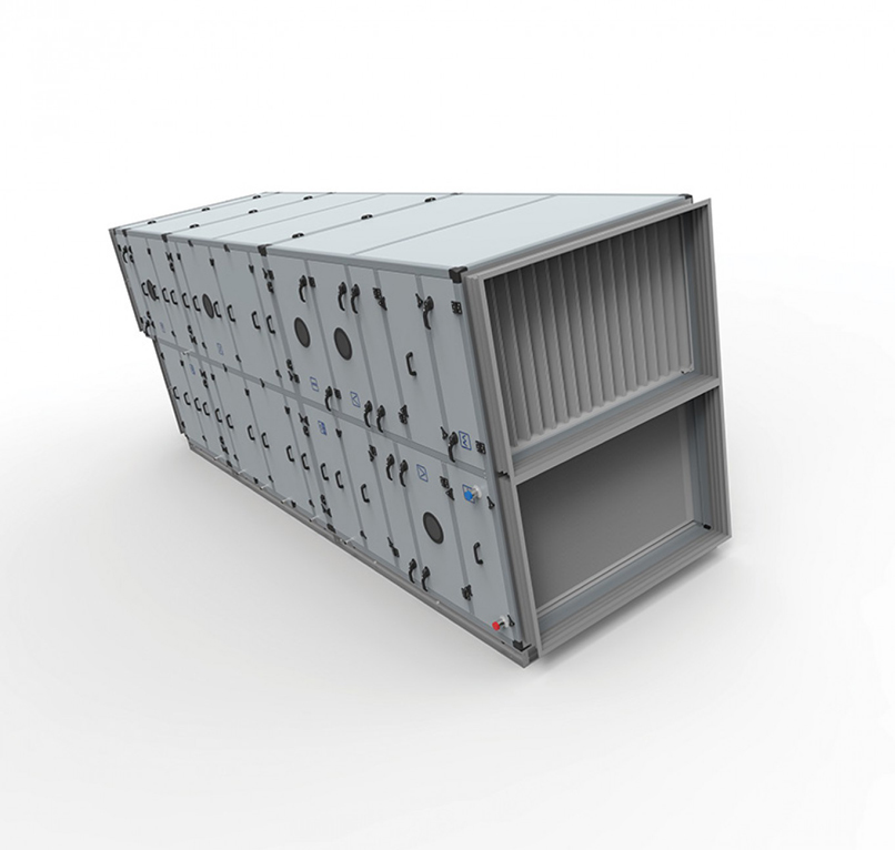
Modular air handling units in pool & industrial execution

Certificates

Selected features of the series EVO-P

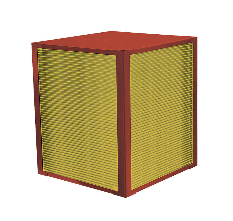
Heat recovery
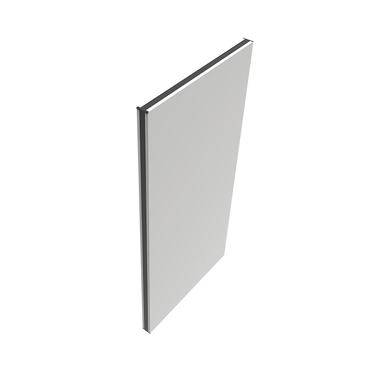
Thermal brake panels
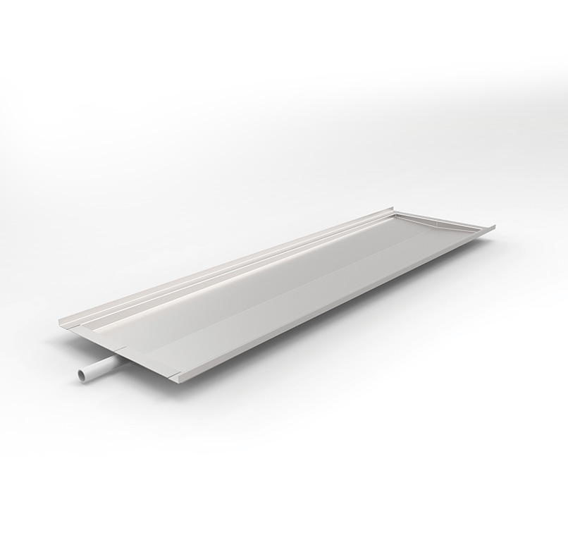
Drain pan
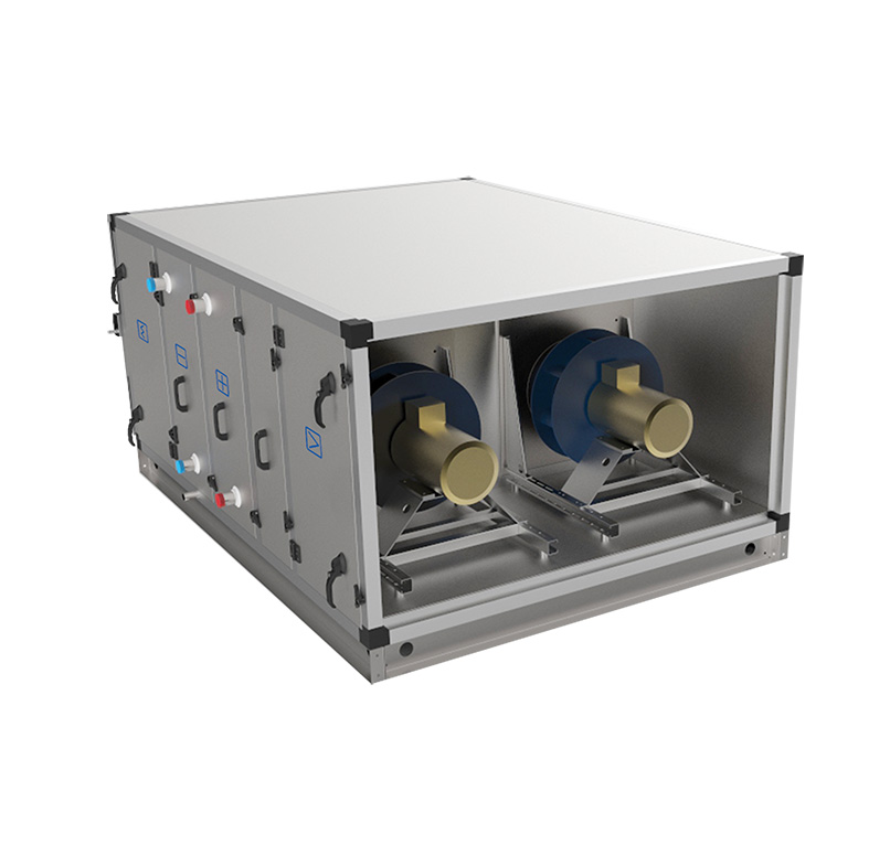
Fan set
Anticorrosive coating
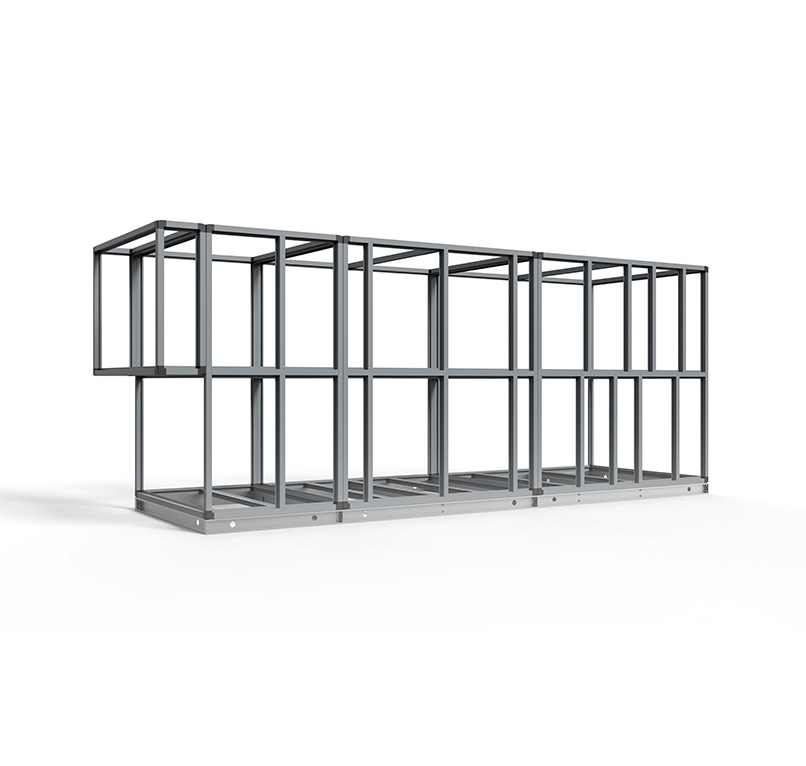
Thermal free frame construction
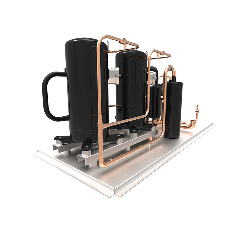
Heat pump module
Heat recovery
  • Plate heat exchanger efficiency up to 75%.
  • Counter-flow plate heat exchanger efficiency up to 92%.
Thermal brake panels
  • Reduction of thermal conductivity
  • Economic benefits
Drain pan
  • Triple sloped
  • Easy maintenance
Fan set
  • Direct driven fans
  • Single or in sets
  • Solutions with AC or EC motors
  • Elimination of the belt drive
Anticorrosive coating
  • Galvanised sheet metal: polyester coated / painted
Thermal free frame construction
  • Made of composite profiles and TBC panels in whole range allowed to achieve thermal transmittance class T2 and thermal bridging class TB2
Heat pump module
  • Build in inverter or digital cooling system

EVO-P components

1
2
3
4
5
6
7
8
1
Framework
  • Advanced composite profiles or high corrosion resistant galvanized steel profiles (insulation version 50), plastic corners.
2
Panels
  • Unique Thermal Brake panels made of galvanized metal sheet 0,7mm thick, covered by polyester coating.
  • Panel thickness of 50mm (floor 70mm) filled with non-combustible mineral wool – A1 class fire protection.
  • Fixed panels riveted to the framework and insulated with sealant.
  • Access panels fixed by clamps, with pull handles.
  • Access doors fixed by clamps (standard) or by handles (optional). Access panels with pull handles fixed by clamps.
  • Sealing access panels-construction by profile gasket.
3
Base frame
  • Foundation foots made from galvanized metal sheet: 5100 ÷ 0300 sizes
  • Base frame made from galvanized metal sheet: 5100 ÷ 0021 sizes
  • Base frame and foundation foots height – 120mm (the trap is included in the height)
4
Drain pan
  • Made of stainless steel, triple sloped, insulated with rubber mat.
  • Recessed in floor.
  • Drainage pipe made of plastic pipe, led out to the side through the AHU’s profile beyond the outline.
  • Universal trap for under and overpressure in the place of operation. It is not required to elevate the frame for the pressure of 600Pa.
5
Guide vanes
  • Made of stainless steel
6
Air dampers
  • Standard aluminium construction. The mechanism hidden in the double profile, separated from external factors.
7
Connections
  • Standard flexible connectors with connectable duct profile.
8
Additional equipment
  • “Dumbo” terminals for pressure switch hoses connection, installed on the AHU’s fixed casing
  • Porthole – fan section, mixing section, filter section, heat pump module are standardly equipped with porthole
  • Lighting – low voltage led technology – option

Functions performed

Close
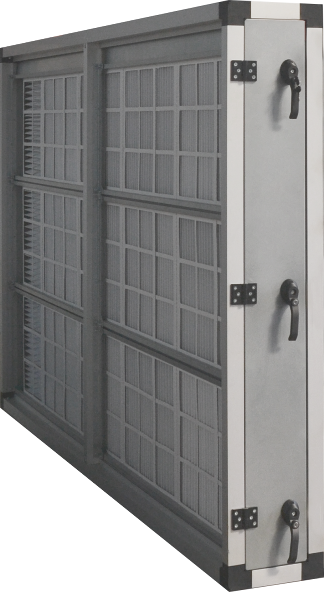
Primary filter
PF
Functions and application

application

An air-conditioning and ventilation systems with standard purity requirements as preliminary filter

An air-conditioning and ventilation systems with strict purity requirements as preliminary and secondary filter

An air-conditioning and ventilation systems with standard or strict purity requirements as the final filtration stage

Catching fat particles and heavy pollutants (metal filter)

type

Metal plate filter

G2 - ISO COARSE

Plate filter:

G4 - ISO COARSE

M5 - ISOePM10-70%

Minipleat filter:

M5 - ISOePM10-70%

F7 - ISOePM2,5-60%

F9 - ISOePM1-80%

Bag filter:

M5 - ISOePM10-50%

F7 - ISOePM2,5-65%

F9 - ISOePM1-70%/80%

Construction

metal filter

Multi layer mesh covered on both sides with galvanized steel mesh mounted in 50mm thick frame

Filteration mesh made of galvanized steel

plate filter

Filter textile covered on both sides with galvanized steel mesh

Mounted in 50mm thick frame

Filter textile made of synthetic polyester filaments

minipleat filter

Mini pleat filter packages with hot melt separators

Mounted in 50/100 mm thick frame

Glass or synthetic fabric refill (100% polypropylene)

bag filter

Pockets sewn and placed on wire truss; bags lenght 300/500mm

Mounted in 25mm thick frame; eccentric crimping

Three-layer synthetic non-woven, polypropylene, using micro fibres

Parameters

 (acc. EN 13053+A1:2011 and EN 779:2012)

metal filter

Filtration grade Am: 80%

End pressure drop Δp: 120Pa

Maximum air velocity v: 4,2m/s

Maximum working temperature: 300°C

plate filter

Filtration grade Am: 82% ÷ 92%

End pressure drop: Δp: 150Pa ÷ 200Pa

Maximum air velocity v: 4,2m/s

Maximum working temperature: 90 ÷ 100°C

minipleat filter

Filtration grade Am: 95% ÷ 99%

Final pressure drop: Δp = 150Pa ÷ 200Pa

Maximum air velocity v: 4,2m/s

Maximum working temperature: 80°C

bag filter

Filtration grade Am: 95% ÷ 99%

Final pressure drop: Δp = 200Pa ÷ 300Pa

Maximum air velocity v: 3,7 ÷ 4,6m/s

Maximum working temperature: 90 ÷ 100°C 

Close
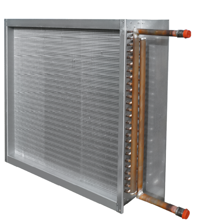
Water heating coil
WH
Functions and application

Application:

  • Heating of supply air in air conditioning and ventilation systems
  • Heating of process air in industry-grade air conditioning and ventilation systems
Construction
  • Copper tubes; aluminium fins (standard) additionaly protected by epoxy coating (EVO-P)
  • Galvanized metal sheet or stainless (EVO-P) frame
  • Mainfolds and connectors made of copper or steel respectively
  • Exchanger connection stub pipes fitted with drain and vent
  • Number of rows: 1 ÷ 6
  • Distance between fins: 1,8 / 2,0 / 2,5mm
  • Fin thickness: 0,1mm
  • Tube wall thickness: 0,37mm
  • Tube diameter: 3/8” ÷ 5/8”


Exchanger medium connection:

  • Connection stub pipes are on the service side of the unit.
  • Medium connection from top or bottom exchanger in order to maintain medium counter flow direction according to the air flow direction.
Parameters

(Conformance to standards: EN 308, EN 1216, EN 13053)

  • Max. medium temperature: 120°C
  • Max. medium working pressure: 1,6MPa = 16bar (tested 21 bar)
  • Max. permitted air flow speed: v = 4,6m/s
  • Max. glycol content: 50%
  • Min./max. temperature of the air: - 40/60°C
  • Protection: permissible minimum temperature of air downstream heat exchanger is monitored by freezing protection thermostat (optional)
  • Heating capacity, pressure losses, etc. available in KAD software
Close
Secondary filter
SF
Functions and application

application

An air-conditioning and ventilation systems with standard purity requirements as preliminary filter

An air-conditioning and ventilation systems with strict purity requirements as preliminary and secondary filter

An air-conditioning and ventilation systems with standard or strict purity requirements as the final filtration stage

Catching fat particles and heavy pollutants (metal filter)

type

Metal plate filter

G2 - ISO COARSE

Plate filter:

G4 - ISO COARSE

M5 - ISOePM10-70%

Minipleat filter:

M5 - ISOePM10-70%

F7 - ISOePM2,5-60%

F9 - ISOePM1-80%

Bag filter:

M5 - ISOePM10-50%

F7 - ISOePM2,5-65%

F9 - ISOePM1-70%/80%

Construction

metal filter

Multi layer mesh covered on both sides with galvanized steel mesh mounted in 50mm thick frame

Filteration mesh made of galvanized steel

plate filter

Filter textile covered on both sides with galvanized steel mesh

Mounted in 50mm thick frame

Filter textile made of synthetic polyester filaments

minipleat filter

Mini pleat filter packages with hot melt separators

Mounted in 50/100 mm thick frame

Glass or synthetic fabric refill (100% polypropylene)

bag filter

Pockets sewn and placed on wire truss; bags lenght 300/500mm

Mounted in 25mm thick frame; eccentric crimping

Three-layer synthetic non-woven, polypropylene, using micro fibres

Parameters

 (acc. EN 13053+A1:2011 and EN 779:2012)

metal filter

Filtration grade Am: 80%

End pressure drop Δp: 120Pa

Maximum air velocity v: 4,2m/s

Maximum working temperature: 300°C

plate filter

Filtration grade Am: 82% ÷ 92%

End pressure drop: Δp: 150Pa ÷ 200Pa

Maximum air velocity v: 4,2m/s

Maximum working temperature: 90 ÷ 100°C

minipleat filter

Filtration grade Am: 95% ÷ 99%

Final pressure drop: Δp = 150Pa ÷ 200Pa

Maximum air velocity v: 4,2m/s

Maximum working temperature: 80°C

bag filter

Filtration grade Am: 95% ÷ 99%

Final pressure drop: Δp = 200Pa ÷ 300Pa

Maximum air velocity v: 3,7 ÷ 4,6m/s

Maximum working temperature: 90 ÷ 100°C 

Close
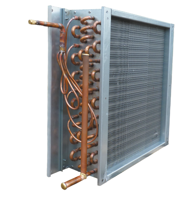
Water cooling coil
WC
Functions and application
  • Cooling of supply air in air conditioning and ventilation systems
  • Cooling of process air in industry-grade air conditioning and ventilation systems
  • Dehumidyfing of process air in industry-grade air conditioning and ventilation systems
Construction
  • Copper tubes; aluminium fins (standard) additionaly protected by epoxy coating (EVO-P)
  • Galvanized metal sheet or stainless (EVO-P) frame
  • Mainfolds and connectors made of copper or steel respectively
  • Exchanger connection stub pipes fitted with drain and vent
  • Number of rows R: 2÷12
  • Distance between fins: 2,5 mm
  • Fin thickness: 0,1mm
  • Tube wall thickness: 0,37 mm
  • Tube diameter: 3/8” ÷ 5/8”
  • Droplet eliminator mounted downstream after the cooler
  • Triple sloped drain pan made of stainless steel, buil-in AHU floor
  • Drain pan equipped with polypropylene ball siphon
Parameters

(Conformance to standards: EN 308, EN 1216, EN 13053)


  • Min. temp. of the medium: +2°C*
  • Max. working pressure of the medium: 1,6MPa = 16bar (tested 21 bar)
  • Max. glycol content: 50%
  • Max. permitted air velocity: v = 4,0 m/s
  • Cooling capacity, pressure drop, etc. available in KAD
Close
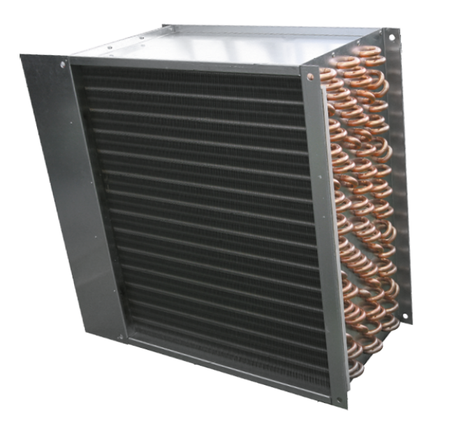
Direct expansion cooling coil
DX
Functions and application
  • Cooling of supply air in air conditioning and ventilation systems
  • Cooling of process air in industry-grade air conditioning and ventilation systems
  • Dehumidyfing of process air in industry-grade air conditioning and ventilation systems
Construction
  • Copper tubes; aluminium fins (standard) additionaly protected by epoxy coating (EVO-P)
  • Single (100%) or double section heat exchanger
  • Galvanized metal sheet or stainless (EVO-P) frame
  • Number of cooler rows R: 2÷10
  • Distance between fins: 2,5mm
  • Fin thickness: 0,1mm
  • Tube wall thickness: 0,37mm
  • Tube diameter: 3/8” ÷ 5/8”
  • Droplet eliminator mounted downstream after the cooler
  • Triple sloped drain pan made of stainless steel, buil-in AHU floor
  • Drain pan equipped with polypropylene ball siphon


Exchanger medium connection

  • Connection stub pipes are on the service side of the unit.
  • Medium connection from top of the exchanger independent of air flow direction
Parameters

(Conformance to standards: EN 308, EN 1216, EN 13053)


  • Min. evaporating temperature of cooling medium evaporation: +3°C*
  • Max. working pressure of the medium up to 2,8MPa = 28bar (tested 32bar)
  • Max. permitted air velocity v = 4,1m/s
  • You can select an exchanger suitable for wide range of refrigerants: R134a, R407c, R410a…
  • Cooling capacity, pressure drops, etc. available in KAD selection software
Close
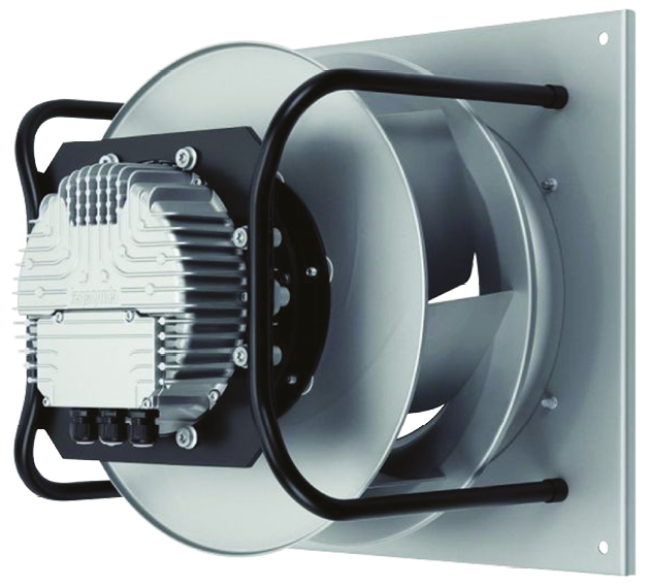
Fan set
VF
Functions and application

Application

  • Low and medium pressure ventilation and air-conditioning systems with overall pressures up to 2 000Pa
  • Medium pressure ventilation and air-conditioning systems with overall pressures up to 3 000Pa (marine industry EVO-M)
  • Applied as a single or multi fan (up to 6 fans sets) solution depends on AHU size and pressure drop


Type

  • AC fan set: SWSI centrifugal fan without casing, one-way suction, PLUG type, with backward curved blades
  • EC fan set: SWSI centrifugal fan without casing, one-way suction, PLUG type, with backward curved blades
  • AC fan set (EVO-M marine execution): DWDI centrifugal fan with casing, two-way suction, with backward curved blade
Construction

AC fan set

  • Fan and motor set on common frame, insulated from unit structure by rubber shock absorbers
  • Direct drive – impeller mounted on motor shaft
  • TEFC single speed motors conforming to IEC standard
  • Suitable for supplying by VFD (variable frequency drive) – optional accessory


EC fan set

  • Fan and motor set on common frame assemled directly to AHU diaphragm
  • Direct drive – impeller mounted on motor shaft
  • Single speed motors conforming to IEC standard
  • Built- in speed amd monitoring controller


AC fan set (EVO-M marine execution)

  • Fan & motor set on common frame, insulated from unit structure by rubber shock absorbers belt drive
  • TEFC marine executiony single speed or two speed motors conforming to IEC standard
  • The motor assambled on tension support
  • Suitable for supplying by VFD (variable frequency drive) – optional accessory
  • The construction and fan epoxy coated protected


Parameters

AC fan set

  • Rated voltage: 3x400V / 50Hz
  • Rated power: 0,75 kW ÷ 15 kW
  • Protection type: PTC
  • Motor winding insulation class: F (matching with frequency converter)
  • Bearing lifecycle: L10 = 20000h / L50 = 100000h
  • Protection class: IP55
  • Efficiency class: IE2 / IE3
  • VFD output frequency range: 10 -100 Hz
  • Min. / max working temperature: -30°C ÷ 55°C


EC fan set

  • Rated voltage: 1x230V / 3x400V / 50Hz
  • Rated power: 0,5 kW ÷ 11,9 kW
  • Motor winding insulation class: B/F respectively (matching with EC controller)
  • Bearing lifecycle: L10 = 40000h / L50 = 200000h
  • Protection class: IP54 / IP55 respectively
  • Efficiency class: above IE3
  • A corresponding sensor with standard analogue output (0 ÷ 10 V or 4 ÷ 20 mA)
  • The open protocol standard RS485 MODBUS-RTU
  • Min. / max working temperature: -25°C ÷ 60°C


AC fan set (EVO-M marine execution)

  • Rated voltage: 1x230 / 3x400V / 3x440 / 3x690 - 50/60Hz
  • Rated power: 0,75 kW ÷ 22,5 kW
  • Protection type: PTC
  • Motor winding insulation class: F (mating with frequency converter)
  • Bearing lifecycle: L10 = 20000h / L50 = 100000h
  • Protection class: IP55
  • Efficiency class: IE2
  • VFD output frequency range: 10 ÷ 100 Hz
  • Min. / max working temperature: -30°C ÷ 55°C


POWER COEFFICIENT DEPENDS ON WORKING TEMPERATURE

Max. ambient temp. °C

30

35

40

45

50

55

60

P/PN %

105

102

100

97

93

87

82

Close
Plate heat exchanger
PR
Functions and application
  • Indirect energy recovery from exhaust air and transfer of such energy to supply air, without possibility of humidity recovery
  • Complete separation of supply air from exhaust air streams
  • Used in combined supply and exhaust units in vertical and horizonatal AHU execution
  • Passive House ready
Construction

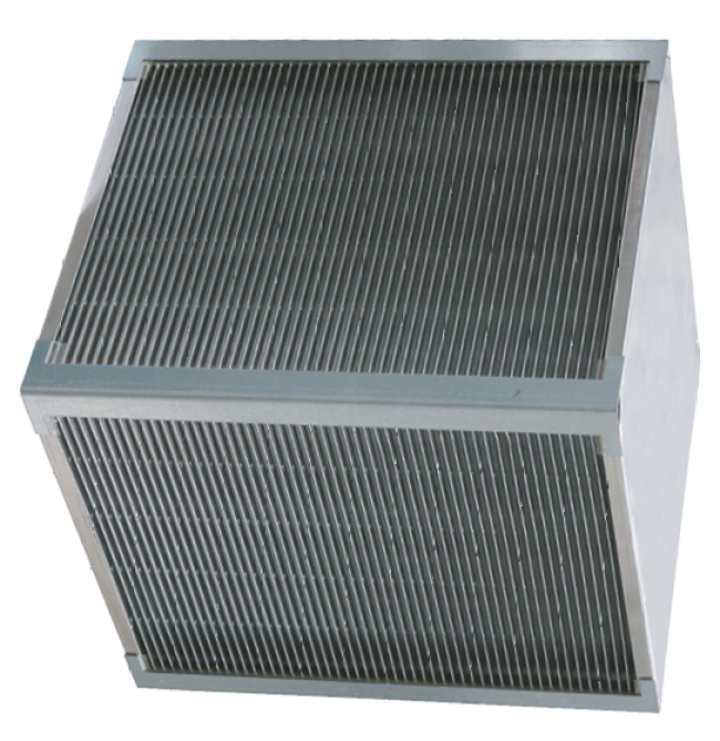
Crossflow plate heat exhanger

  • The block is made of aluminium plates (EVO-S / EVO-H) additionaly epoxy coated (EVO-P) with separated supply and exhaust air streams flowing between them
  • 100% by-pass with installed air damper allows to “avoid” the exchanger, that is:
  • Accordingly to decrease or “to switch off” energy recovery
  • Protect the exchanger against freezing
  • Droplet separator with triple sloped drain pan built-in AHU floor
  • Drain pan equipped with polypropylene ball siphon
Parameters

(Conformance to standards: EN 308, EN 13053)


Crossflow plate heat exhanger

  • Max. air volume flow: 60 000 ÷ 70 000m3/h
  • Efficiency: up to 75%
  • Heat-exchanger tightness for rated working parameters (250Pa) 99,9%
  • Max. air velocity: 4,5m/s
  • Max. pressure drop: 450Pa
  • Permitted pressure difference: 2000 Pa
  • Min. / max. working temperature: -40 ÷ 80°C
Close
Run around glycol system
RG
Functions and application

Application

  • Indirect energy recovery (sensible heat) at complete (100%) separation of supply and exhaust air streams mainly dedicated to medical and industry applications
  • Supply air and extract air heat exchangers can be arranged at entirely separate locations.


Type

  • Exchangers installed in common casing, with complete hydraulic installation (monoblock AHU)
  • Exchangers separated from one another (supply and exhaust units separated from one another)
Construction
  • A block of two exchangers - one of them is in the exhaust air stream, collecting heat (cooler) and transferring it, by intermediate medium (brine), onto the exchanger installed in the supply air stream (heater)
  • Exchanger placed in the exhaust air stream is equipped with droplet separator and triple sloped drain pan buil-in AHU floor
  • Construction of individualy designed very high counterflow for maximum heat transfer Cu/Al. special exchangers
  • Each vent and drain of the heat exchanger circuit is easly accessible via additional inspection panels.
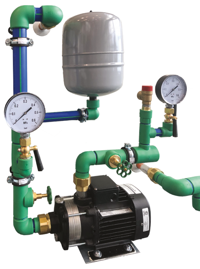
  • Hydraulic installation made of anti-corrosive and suitable for water/glycol medium and equipped with expansion tank and VFD controlled circulation pump
  • Connection pipes are on the service side of the unit
  • Drain pan equipped with polypropylene ball siphon
Parameters

(Conformance to standards: EN 308, EN 13053)


  • SEfficiency: up to 76%
  • Max. permissible air velocity:
    - Heater: v = 4,6m/s
    - Cooler: v = 4,1m/s
  • Max. working pressure of the medium: 1,6MPa = 16bar (tested 21 bar)
  • Min. temperature of the medium depends on glycol content concentration
  • Glycol content: max. 50%
  • Pressure losses on exchangers/medium flow etc. available in KAD software
Close
Counterflow plate heat exchanger
CPR
Functions and application
  • Indirect energy recovery from exhaust air and transfer of such energy to supply air, without possibility of humidity recovery
  • Complete separation of supply air from exhaust air streams
  • Used in combined supply and exhaust units in vertical and horizonatal AHU execution
  • Passive House ready
Construction

Counterflow plate heat exchanger

  • The block is made of aluminium plates (EVO-S / EVO-H) additionaly epoxy coated (EVO-P) with separated supply and exhaust air streams flowing between them
  • 100% by-pass with installed air damper allows to “avoid” the exchanger, that is:
    - Accordingly to decrease or “to switch off” energy recovery
    - Protect the exchanger against freezing
  • Droplet separator with triple sloped drain pan built-in AHU floor
  • Drain pan equipped with polypropylene ball siphon
Parameters

(Conformance to standards: EN 308, EN 13053)


Counterflow plate heat exchanger

  • Max. air volume flow: 20 000m3/h
  • Efficiency: up to 92%
  • Heat-exchanger tightness for rated working parameters (250Pa) 99,5%
  • Max. air velocity: 4,5m/s
  • Max. pressure drop: 400Pa
  • Permitted pressure difference: 800Pa
  • Min. / max. working temperature: -40 ÷ 80°C
Close
Silencer
SL
Functions and application

Application

  • Installed in-to the AHU to ensure noise reduction downstream of the fan set


Type

  • SLC_STD (standardowy)
  • SLC_HEFF (wyższa skuteczność)
Construction
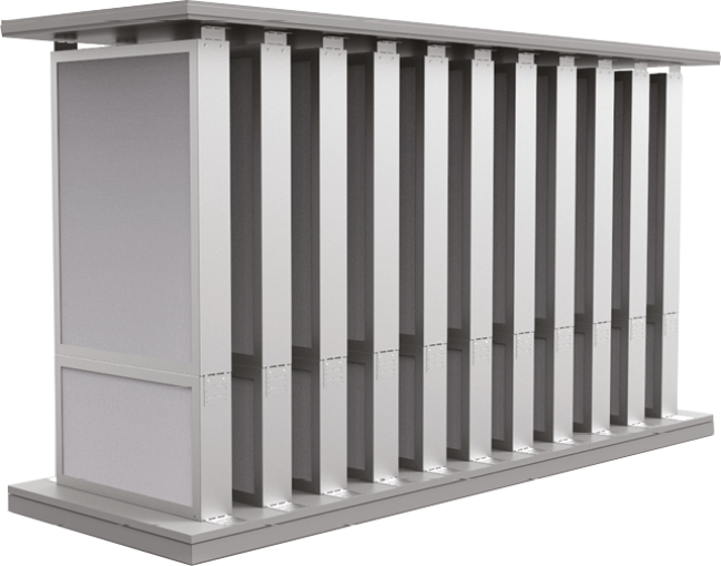
  • The block is fitted with silencing cartridges made of non-flammable mineral wool, 100 or 200mm thick
  • The surface of wool insert protected with veil
  • Mineral wool fulfillment is built by galvanized metal sheet frame (add. pliester coated EVO-H)
Parameters

Max. permitted air velocity: v = 4,5m/s

Accesories

Roof / Intake / Outtake

  • For outside unit is delivered roof and component of the intake and outtake
  • Components with water drainage to the side opposite from the viewing side can be additionally installed on AHU


Door Locks and Handles

  • Easy to use door locks and handles ensure safe unit maintenance


Inspection window

  • Inspection window enables to observe unit‘s internal operation. The diameter of plastic porthole is 200mm
  • The porthole could be use with darkwork (in option)


Internal lighting

  • Internal lighting enables to observe unit‘s internal operation through inspection window.
  • Economy light is used with switch outside the unit
Close
Cooling module
CM
Functions and application

Application

  • Cooling module CM - cooling of air supply in ventilation and air conditioning systems
  • Heat pump module HPM - heating or cooling of air supply in ventilation and air conditioning systems
  • Cooling module or Heat pump module are offered as an hybrid solution in combination with energy recovery solution only: Counterflow or Plate Heat Exchanger (CPR, PR), Rorary Regenerator (RR),
    Run-Around Coil (RG)


Type

  • CMi/HPMi EVO (inverter)
  • CMd/HPMd EVO (digital)
Construction
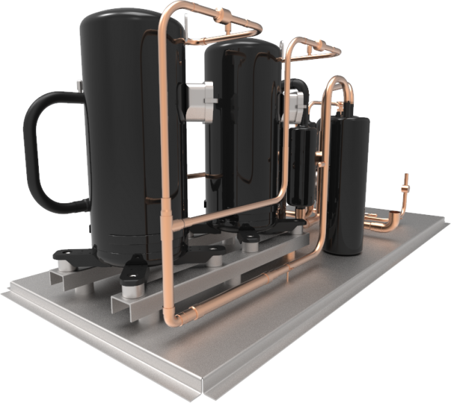
  • Modules are installed inside the AHU
  • It comprise two sections: compressor section (compressor with accessories) and liquid section (liquid tank with accessories)
  • The refrigerant mas flow is controlled by electronic expansion valve
  • Compressors are adequately protected with low-pressure and high-pressure switches
  • Cooling system is delivered with complete control system
  • Pressure switches and pressure gauges are installed in isolated space, separated from the air stream
Parameters

CMi/HPMi EVO

  • Rated voltage: 3x400V / 50Hz
  • Compressor type: DC inverter (up to 30 kW)
  • Compressor type: DC Inverter+on/off (above 30 kW)
  • Air volume flow: 1 700 ÷ 76 000 m3/h
  • Cooling capacty Qc: 7 ÷ 175 kW
  • Heating capacity Qh: 6 ÷ 140 kW
  • EER* ratio: up to 7
  • COP* ratio: up to 24
  • Cooling refrigerant: R410a or R407c respectively


CMd/HPMd EVO

  • Rated voltage: 3 x 400V / 50Hz
  • Compressor type: Digital Scroll (up to 30 kW)
  • Compressor type: Digital Scroll+on/off (above 30 kW)
  • Air volume flow: 2000 ÷ 18000 m3/h
  • Cooling capacty Qc: 7 ÷ 63 kW
  • Heating capacity Qh: 8 ÷ 46 kW
  • EER* ratio: up to 7
  • COP* ratio: up to 24

*Efficiency ratio calculated in combination of coolling module and energy recovery system

Close
Heat pump module
HPM
Functions and application

Application

  • Cooling module CM - cooling of air supply in ventilation and air conditioning systems
  • Heat pump module HPM - heating or cooling of air supply in ventilation and air conditioning systems
  • Cooling module or Heat pump module are offered as an hybrid solution in combination with energy recovery solution only: Counterflow or Plate Heat Exchanger (CPR, PR), Rorary Regenerator (RR),
    Run-Around Coil (RG)


Type

  • CMi/HPMi EVO (inverter)
  • CMd/HPMd EVO (digital)
Construction
  • Modules are installed inside the AHU
  • It comprise two sections: compressor section (compressor with accessories) and liquid section (liquid tank with accessories)
  • The refrigerant mas flow is controlled by electronic expansion valve
  • Compressors are adequately protected with low-pressure and high-pressure switches
  • Cooling system is delivered with complete control system
  • Pressure switches and pressure gauges are installed in isolated space, separated from the air stream
Parameters

CMi/HPMi EVO

  • Rated voltage: 3x400V / 50Hz
  • Compressor type: DC inverter (up to 30 kW)
  • Compressor type: DC Inverter+on/off (above 30 kW)
  • Air volume flow: 1 700 ÷ 76 000 m3/h
  • Cooling capacty Qc: 7 ÷ 175 kW
  • Heating capacity Qh: 6 ÷ 140 kW
  • EER* ratio: up to 7
  • COP* ratio: up to 24
  • Cooling refrigerant: R410a or R407c respectively


CMd/HPMd EVO

  • Rated voltage: 3 x 400V / 50Hz
  • Compressor type: Digital Scroll (up to 30 kW)
  • Compressor type: Digital Scroll+on/off (above 30 kW)
  • Air volume flow: 2000 ÷ 18000 m3/h
  • Cooling capacty Qc: 7 ÷ 63 kW
  • Heating capacity Qh: 8 ÷ 46 kW
  • EER* ratio: up to 7
  • COP* ratio: up to 24

*Efficiency ratio calculated in combination of coolling module and energy recovery system

Close
Empty section
ES
Close
Mixed section
MX
PF
Primary filter
WH
Water heating coil
SF
Secondary filter
WC
Water cooling coil
DX
Direct expansion cooling coil
VF
Fan set
PR
Plate heat exchanger
RG
Run around glycol system
CPR
Counterflow plate heat exchanger
SL
Silencer
CM
Cooling module
HPM
Heat pump module
ES
Empty section
MX
Mixed section

Application

Industry
Swimming pools
Processing industry
Chemical industry

Technical data

SIZE

VMIN

VOPT

VMAKS

EXTERNAL DIMENSIONS

SUPPLY OR EXHAUST UNITS

SUPPLY EXHAUST UNITS

W

H

HTOT

W1

H1

H1TOT

0300

1408

2800

6334

950

600

720

2400

1150

1270

0400

1822

3750

8197

1200

600

720

2400

1150

1270

2500

2419

500

10886

1300

700

8920

2600

1350

1470

3500

2 479

4 900

11 154

950

950

1070

1 900

1 850

1 970

0600

2 851

5 900

12 830

1 300

800

920

2 600

1 550

1 670

0700

3 326

7 000

14 969

1 500

800

920

3 000

1 550

1 670

5800

4 082

8 300

18 371

1 500

950

1070

3 000

1 850

1 970

8800

4 198

8 000

18 889

1 200

1 200

1 320

2 400

2 350

2 470

0010

4 666

9 700

20 995

1 700

950

1 070

3 400

1 850

1 970

5010

5 011

9 800

22 550

1 300

1 300

1 420

2 600

2 550

2 670

5310

6 487

13 400

29 192

1 800

1 200

1 320

3 600

2 350

2 470

4410

6 854

14 200

30 845

1 500

1 500

1 620

3 000

2 950

3 070

5610

7 934

16 500

35 705

2 000

1 300

1 420

4 000

2 550

2 670

0020

9 605

20 000

43 222

2400

1300

1420

4 800

2 600

2 720

0120

10 159

21 000

45 716

1 800

1 800

1 920

3 600

3 600

3 270

5320

11 261

24 000

50 674

2 400

1 500

1 620

4 800

3 000

3 120

0720

12 722

27 000

57 251

2 000

2 000

2 120

4 000

4 000

4 120

0230

15 163

32 500

68 234

2 800

1 700

1 820

5 600

3 400

3 520

0530

16 848

36 000

75 816

3 100

1 700

1 820

6 200

3 400

3 520

0930

18 713

40 000

84 208

2 400

2 400

2 520

4 800

4 800

4 920

0040

20 088

45 000

90 396

3 100

2 000

2 120

6 200

4 000

4 120

0050

24 106

54 500

108 475

3 700

2 000

2 120

7 400

4 000

4 120

Files to download

Klimor Air Designer

The web-based software offers a quick selection of products according to the specific design requirements. The software provides users with all necessary technical information.
Go to the configurator